My son Paul is the author of this guest post.
This Arduino sketch is useful for rescuing ATtiny microcontrollers rendered useless by incorrect fuse settings. It does this by putting the bricked tiny into high-voltage serial programming mode and writing the fuses to safe values.
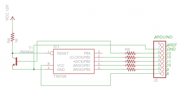
Connection Diagram
The Arduino is connected to the tiny though 1k resistors and a 2N3904 transistor is used to switch 12 volts applied to the tiny’s reset pin. After uploading the sketch the Arduino sends “Enter a character to continue.” repeatedly until communications are established by sending a byte through the serial monitor. The Arduino then programs the fuses.
Serial Monitor log
Enter a character to continue.
Enter a character to continue.
Enter a character to continue.
1
Entering programming Mode
lfuse reads as 62
hfuse reads as 5F
efuse reads as FF
Writing hfuse
Writing lfuse
lfuse reads as 62
hfuse reads as DF
efuse reads as FF
Exiting programming Mode
Download the program: hv_serial_prog.pde
Based on work by Jeff Keyzer.
Let me know if it works for you.

Works like a charm.
My AtTiny13 was bricked due to a corrupted Boards.txt file. I fixed it with your sketch.
My implementation on a breadboard was:
– 1K resistors for R1-R4
– 18k for R5
– BC547B for T1 (most general purpose NPN will do 546,548)
– A 12V LED power supply
Thank you for sharing!
Thanks so much! I just rescued 4 attiny85’s!!!
Works fine.
Thank you.
I pulled up by 10k at IO13 for just in case.
Thank you for sharing!
Hi All,
In order to reset the fuses on the ATTINY24 use this pinout.
//SDI PA6 I Serial Data Input (pin 7)
//SII PA5 I Serial Instruction Input (pin 8)
//SDO PA4 O Serial Data Output (pin 9)
//SCI PB0 I Serial Clock Input (pin 2)
//must ground pins 11,12,13)
Hello, I’m wondering what the !! in this code snippet does:
if (bitOrder == LSBFIRST) {
digitalWrite(dataPin, !!(val & (1 << i)));
Is it a not not ?
Thanks and great code !
thanks, this saved my attiny44. i had to program it in-circuit as it was a soldered down soic-14.
i ran into issues using the arduino to power the target, though. it just hung at “Entering program mode”.
the solution was to connect the target attiny44’s power directly up to 3.3v out on the arduino, then it was able to communicate.
not sure if it was too low current or what.
btw, on this chip CLOCK/PB3 actually needed to go to pin #2 on the attiny – (PCINT8/XTAL1/CLKI) PB0. i was able to connect the other 6 pins to the corresponding pins on the target’s ISP header.
Thanks . Worked for me.
this is super …….. thanks soo much….